
Gear Operated Butterfly Valve for Fire Protection — Wafer Type DN50–DN300
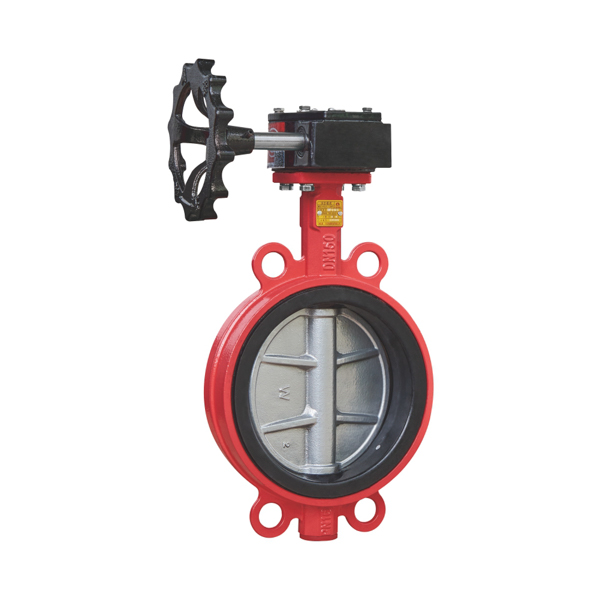
The CA-FIRE gear operated butterfly valve (ZSDF7 / ZSXDF7 series) is a worm gear actuated wafer butterfly valve designed for fire sprinkler systems, standpipe systems, and foam suppression pipelines. Available in three variants — with tamper switch (ZSXDF7), without tamper switch (ZSDF7), and lockable (ZSDF7-L) — all in DN50 through DN300, rated at 1.6 MPa working pressure.
The gear operated butterfly valve uses a multi-turn worm gear (涡轮蜗杆) handwheel that reduces operating torque on larger valve sizes, making it the preferred actuator type for DN100 and above on fire water mains, pump discharge headers, and zone control valve assemblies. The compact wafer design installs between standard ANSI, DIN, or GB flanges with minimal face-to-face length.
This page covers wafer type gear operated butterfly valves (ZSDF7 / ZSXDF7). For grooved Victaulic-compatible butterfly valves, see the Grooved Butterfly Valve page. For hazardous area installations requiring Ex certification, see the Explosion Proof Butterfly Valve page.
Key Features of the ZSDF7 / ZSXDF7 Gear Operated Butterfly Valve
- Worm gear (涡轮) actuator reduces operating torque by 60–80% compared to direct lever operation — essential for DN150 and larger valves on high-pressure fire mains
- Three model variants in one family: ZSXDF7 with DC24V tamper switch, ZSDF7 without switch, and ZSDF7-L with integrated lockout device — specify by supervision requirement, not by product family
- ZSXDF7 tamper switch outputs open/closed position signal to fire alarm control panel (FACP) — satisfies NFPA 72 Chapter 17 and GB 50116 electrical supervision requirements
- ZSDF7-L lockable version accepts standard padlock through the gear housing lock tab — satisfies NFPA 13 physical supervision (lock-open) requirement for non-supervised zones
- Wafer type installation between ANSI 150 / DIN PN16 / GB PN16 flanges — face-to-face 45–80 mm depending on DN size
- Cast iron GGG40 or stainless steel SS316 body — same model number, different material suffix
- EPDM resilient seat standard — rated for water and foam-water mixture at 4–80°C (signal version), compatible with AFFF and AR-AFFF
- Full port design — disc in open position presents minimal flow restriction, reducing system pressure loss on fire water mains
- Compliant with GB 5135.13 (signal butterfly valve) and GB 5135.2 (non-signal butterfly valve) fire protection valve standards
Technical Specifications — ZSXDF7 / ZSDF7 / ZSDF7-L Comparison
The table below compares all three wafer gear operated butterfly valve models. Select the appropriate variant based on the supervision method required by your project specification.
| Parameter | ZSXDF7 (With Signal) | ZSDF7 (No Signal) | ZSDF7-L (Lockable) |
| Model Number | ZSXDF7-Q-50-300-16 | ZSDF7-Q-50-300-16 | ZSDF7-L-Q-50-300-16 |
| Nominal Diameter | DN50–DN300 | DN50–DN300 | DN50–DN300 |
| Working Pressure | 1.6 MPa | 1.6 MPa | 1.6 MPa |
| Strength Test | 6.4 MPa | 6.4 MPa | 6.4 MPa |
| Seal Test | 3.2 MPa | 3.2 MPa | 3.2 MPa |
| Media | Water, foam-water | Water, foam-water | Water, foam-water |
| Actuator | Worm gear (涡轮) | Worm gear (涡轮) | Worm gear + lockout (带锁) |
| Tamper Switch | DC24V 0.5A (open/closed) | None | None (padlock locking) |
| Signal Output | Yes — to FACP | No | No (physical lock supervision) |
| Body Material | Cast iron GGG40 / SS316 | Cast iron GGG40 / SS316 | Cast iron GGG40 / SS316 |
| Connection | Wafer (between flanges) | Wafer (between flanges) | Wafer (between flanges) |
| Temperature Range | 0–80°C | 4–70°C | 4–70°C |
| Typical Use | Electrically supervised fire mains | Manual isolation, non-supervised zones | Physically locked-open per NFPA 13 |
Structural Dimensions — Wafer Type Face-to-Face Length
The wafer gear operated butterfly valve installs between two pipe flanges. The face-to-face dimension is the valve body thickness (not including the handwheel or gear housing). Bolt length must account for the valve face-to-face length plus both flange thicknesses.
| DN (mm) | 50 | 65 | 80 | 100 | 125 | 150 | 200 | 250 | 300 |
| Face-to-Face (mm) | 45 | 50 | 50 | 55 | 60 | 60 | 65 | 70 | 80 |
How the Gear Operated Butterfly Valve Works
The ZSDF7 series gear operated butterfly valve uses a worm-and-wheel (蜗轮蜗杆) gear pair to transmit handwheel rotation to the valve stem at a mechanical advantage. Here is the full operating sequence:
- Handwheel rotation: Turning the handwheel clockwise closes the valve; counterclockwise opens it. The worm gear reduces input torque by a 15:1 to 30:1 ratio depending on valve size — a DN300 valve that would require over 150 Nm of direct lever torque can be operated with approximately 20 Nm via the worm gear.
- Quarter-turn disc rotation: The gear output shaft rotates the butterfly disc 90° between full-open (parallel to flow) and full-closed (perpendicular to flow) positions. Travel stops are machined into the gear housing to prevent over-rotation and seat damage.
- Tamper switch activation (ZSXDF7 only): A cam on the valve stem actuates the supervisory switch microswitch. When the disc is in the fully open position, the switch sends a continuous ‘OPEN’ signal to the FACP. Any movement of the disc from full-open causes the switch to change state within 1–2 handwheel turns, transmitting a ‘TAMPER’ supervisory alarm per NFPA 72.
- Lockout (ZSDF7-L only): The lockable gear housing includes a lock tab that accepts a standard padlock (shackle diameter ≤ 8 mm). When locked in the open position, the valve satisfies NFPA 13 Section 8.16.1 physical supervision requirement. The lock must be removed before the valve can be closed, providing a physical barrier against accidental closure.
- Position indicator: All ZSDF7 and ZSXDF7 variants include a visual position indicator arrow on top of the gear housing. The arrow aligns with the pipe centerline when open and perpendicular when closed — visible from ground level on overhead fire mains without a ladder.
Applications
The gear operated butterfly valve is the most widely specified valve type in commercial and industrial fire suppression systems. Typical applications for the ZSDF7 / ZSXDF7 wafer series include:
- Fire sprinkler system control valves — zone control valve (ZCV) assemblies on wet pipe, dry pipe, and pre-action sprinkler systems per NFPA 13. The ZSXDF7 tamper switch connects to the fire alarm panel for mandatory supervisory monitoring.
- Standpipe system isolation valves — floor control valves on high-rise standpipe systems where gear operation is preferred over lever for ease of use with large-diameter risers (DN150–DN250).
- Fire pump discharge headers — isolation and test line valves on fire pump sets. The gear operator provides controlled, slow opening to prevent water hammer on startup.
- Foam concentrate supply lines — tank farm and aircraft hangar foam suppression headers. EPDM seat is compatible with AFFF, AR-AFFF, and 3% protein foam at full working pressure.
- Water storage tank outlets — suction line isolation on fire water storage tanks and elevated storage tanks. ZSDF7-L lockable version is specified where physical lock-open supervision is required.
- Commercial building fire mains — riser isolation valves in multi-story commercial buildings, hotels, and shopping malls where NFPA 13 electrical supervision is required by the AHJ.
- Industrial deluge systems — isolation valves on deluge valve trim piping and water supply headers where the gear operator provides repeatable, torque-controlled operation.
- Marine and offshore fire mains — stainless steel SS316 body version specified for shipboard fire main isolation and offshore platform fire water distribution headers.
Which Model to Specify: ZSXDF7 vs. ZSDF7 vs. ZSDF7-L
All three gear operated butterfly valve models share the same body, disc, seat, and gear actuator. The only difference is the supervisory mechanism. Use this guide to match the model to your project supervision requirement:
Specify ZSXDF7 (With Tamper Switch) when:
- The project specification requires electrically supervised water supply control valves per NFPA 13 Section 8.16.1(1) or equivalent local code
- A fire alarm control panel (FACP) is installed and the AHJ requires supervisory signal monitoring of all water supply valves
- The building has a monitored fire alarm system connected to a UL-listed central station — NFPA 72 requires supervisory signal transmission for tampered valves
- The project is a high-rise, hospital, detention facility, or other occupancy where NFPA 101 mandates full fire alarm supervision
Specify ZSDF7 (No Tamper Switch) when:
- The valve is in a non-supervised zone and physical access control (locked mechanical room) provides adequate security per the AHJ’s interpretation
- The system is a small standalone fire pump test loop, drain valve, or auxiliary line where supervisory monitoring is not required by the project specification
- Cost is a primary constraint and the AHJ has accepted a lock-open or seal-open alternative to electrical supervision for the specific valve location
Specify ZSDF7-L (Lockable, No Switch) when:
- NFPA 13 Section 8.16.1(2) physical supervision (locked open) is the specified method — typically in smaller buildings or systems not connected to a monitored FACP
- The valve is in a mechanically locked room or enclosure that itself satisfies the ‘locked open’ supervision requirement per the local AHJ
- A retrofit project requires replacing an existing locked-open gate valve with a modern butterfly valve — the ZSDF7-L is a direct functional equivalent
Gear Operated vs. Lever Operated: How to Choose
CA-FIRE offers both gear operated (ZSDF7 / ZSXDF7) and lever operated (ZSDF7-S / ZSXDF7-S) wafer butterfly valves. Both share identical body, disc, seat, and pressure ratings. The actuator type determines which is right for your application:
| Gear Operated (This Page) | Lever Operated | |
| Actuation | Worm gear handwheel | Direct lever handle |
| Torque | Multi-turn — better for larger DN | Single quarter-turn — fast, small DN |
| Best for DN | DN100 and above | DN50–DN150 |
| Locking | Optional lockout device (ZSDF7-L) | Optional padlock on lever |
| Signal version | ZSXDF7 (tamper switch) | ZSXDF7-S (tamper switch) |
| See page | Current page | /product/lever-butterfly-valve/ |
General rule: use gear operated for DN100 and above on fire water mains; use lever operated for DN50–DN80 on branch lines and zone isolations where fast manual operation is more important than torque reduction.
Installation Notes
- Orientation: The gear operated butterfly valve can be installed in any orientation — horizontal pipe, vertical pipe, or inclined. The gear housing weight does not affect disc seating.
- Flange bolt pattern: The wafer valve requires four bolts minimum per flange pair. Use full-length through-bolts that pass through both flanges and the valve body lugs. Bolt length = valve face-to-face + (2 × flange thickness) + nut height.
- Flow direction: The ZSDF7 series is bi-directional. Either end can be upstream. However, for vertical pipe with downward flow, ensure the gear housing is accessible from the maintenance walkway.
- Clearance: Gear housing height above pipe centerline varies by DN size — allow 250–450 mm above the pipe for handwheel clearance. Check structural obstruction clearance before final valve positioning.
- Signal wiring (ZSXDF7 only): Connect the tamper switch via a 2-wire, end-of-line supervised circuit to a supervisory zone on the FACP. Cable entry via M20 × 1.5 thread conduit connector. Maximum cable run: 300 m (0.5 mm² conductor) without signal booster.
- Lock (ZSDF7-L only): After hydrostatic testing and system commissioning, lock the valve in the fully open position with a padlock (shackle ≤ 8 mm diameter). Record padlock serial number in the valve tag record per NFPA 25 inspection requirements.
Frequently Asked Questions
What is a gear operated butterfly valve?
A gear operated butterfly valve uses a worm gear (蜗轮蜗杆) mechanism to convert multi-turn handwheel rotation into a quarter-turn disc movement. The worm gear provides a mechanical advantage that reduces the torque required to operate the valve — especially important for large diameter (DN100+) fire water valves at full system pressure. In fire protection, the gear operated butterfly valve is the standard actuator type for main water supply isolation valves, zone control valves, and fire pump headers.
How does the worm gear butterfly valve differ from a standard butterfly valve?
A standard butterfly valve has a direct lever that rotates 90° in a single quarter-turn motion. A worm gear butterfly valve replaces the lever with a multi-turn handwheel connected via a worm-and-wheel gear pair. The gear ratio (typically 15:1 to 30:1) means the handwheel must be turned 15–30 full rotations to move the disc 90°. This reduces required operating torque by the same ratio — making it practical to operate large valves against full fire system pressure without excessive effort.
Does the ZSXDF7 gear operated butterfly valve comply with NFPA 13?
Yes. NFPA 13 Section 8.16 requires that all water supply control valves be supervised by one of four methods: (1) electrical tamper switch, (2) locked open, (3) sealed open, or (4) located in a constantly attended location. The ZSXDF7 satisfies method (1) electrical supervision via its built-in DC24V tamper switch. The ZSDF7-L satisfies method (2) locked open. The ZSDF7 (no switch, no lock) can satisfy method (3) or (4) depending on AHJ acceptance.
What is the difference between ZSDF7 and ZSXDF7?
ZSDF7 is the gear operated wafer butterfly valve without a supervisory switch (涡轮对夹蝶阀). ZSXDF7 is the gear operated wafer butterfly valve with a built-in DC24V tamper switch (涡轮对夹信号蝶阀). The ‘信号’ (signal) in the Chinese name refers to the electrical supervisory signal output. All other specifications — body, disc, seat, gear actuator, pressure rating, and size range — are identical between ZSDF7 and ZSXDF7. Choose ZSXDF7 when electrical supervision is required; ZSDF7 when it is not.
What size worm gear butterfly valve do I need?
Valve size is determined by the fire system hydraulic calculation, not the valve’s own specifications. The ZSDF7 / ZSXDF7 series covers DN50–DN300 (NPS 2–12″). Most sprinkler system risers require DN100–DN150 (NPS 4–6″). Pump discharge headers typically range from DN150–DN250. Tank farm foam headers use DN200–DN300. Your fire protection engineer will specify the required pipe and valve size based on flow rate, working pressure, and system design standard.
Can the gear operated butterfly valve be used for throttling flow?
The gear operated butterfly valve is designed primarily as an on/off isolation valve for fire protection service. It can be partially opened to throttle flow during system testing and commissioning, but it is not designed for continuous throttling service at partially open positions. Prolonged operation at partial opening causes accelerated seat wear and disc erosion. For flow control applications, specify a dedicated control valve; use the ZSDF7 / ZSXDF7 exclusively for open/closed isolation service.
Standards & Compliance References
The CA-FIRE ZSDF7 / ZSXDF7 gear operated butterfly valve is designed and tested in compliance with the following standards:
- NFPA 13 — Standard for the Installation of Sprinkler Systems: https://www.nfpa.org/codes-and-standards/nfpa-13 (Section 8.16 water supply control valve supervision)
- NFPA 72 — National Fire Alarm and Signaling Code: https://www.nfpa.org/codes-and-standards/nfpa-72 (Chapter 17 supervisory signal initiating devices)
- NFPA 25 — Standard for the Inspection, Testing, and Maintenance of Water-Based Fire Protection Systems: https://www.nfpa.org/codes-and-standards/nfpa-25 (valve inspection and lock records)
- IEC 60534-2-1 — Industrial-process control valves (flow capacity): https://www.iec.ch (referenced for Cv/Kv flow coefficient calculation)
- GB 5135.13 — Fire Protection Valves, Part 13: Signal Butterfly Valves: https://www.gb688.cn (Chinese national standard — ZSXDF7)
- GB 5135.2 — Fire Protection Valves, Part 2: Non-Signal Butterfly Valves: https://www.gb688.cn (Chinese national standard — ZSDF7 / ZSDF7-L)
Related Products
If your project requires a different connection type or hazardous area certification, see the related products below:
| If You Need → | Grooved Connection | Hazardous Area (Ex certified) |
| Connection | Grooved (Victaulic-compatible) | Wafer or Grooved |
| Ex Certification | Not required | Ex db IIC T6 Gb required |
| See page → | /product/grooved-butterfly-valve/ | /product/explosion-proof-butterfly-valve/ |
Request a Quote or Technical Datasheet
Email: sales@ca-fire.com
Mobile: +86 13400715622
WhatsApp: +86 18150362095
WeChat: 404863577
Website: https://www.ca-fire.com
Technical Specifications — ZSXDF7 / ZSDF7 / ZSDF7-L Comparison
| Parameter | ZSXDF7 (With Signal) | ZSDF7 (No Signal) | ZSDF7-L (Lockable) |
| Model Number | ZSXDF7-Q-50-300-16 | ZSDF7-Q-50-300-16 | ZSDF7-L-Q-50-300-16 |
| Nominal Diameter | DN50–DN300 | DN50–DN300 | DN50–DN300 |
| Working Pressure | 1.6 MPa | 1.6 MPa | 1.6 MPa |
| Strength Test | 6.4 MPa | 6.4 MPa | 6.4 MPa |
| Seal Test | 3.2 MPa | 3.2 MPa | 3.2 MPa |
| Media | Water, foam-water | Water, foam-water | Water, foam-water |
| Actuator | Worm gear (涡轮) | Worm gear (涡轮) | Worm gear + lockout (带锁) |
| Tamper Switch | DC24V 0.5A (open/closed) | None | None (padlock locking) |
| Signal Output | Yes — to FACP | No | No (physical lock supervision) |
| Body Material | Cast iron GGG40 / SS316 | Cast iron GGG40 / SS316 | Cast iron GGG40 / SS316 |
| Connection | Wafer (between flanges) | Wafer (between flanges) | Wafer (between flanges) |
| Temperature Range | 0–80°C | 4–70°C | 4–70°C |
| Typical Use | Electrically supervised fire mains | Manual isolation, non-supervised zones | Physically locked-open per NFPA 13 |
Structural Dimensions — Wafer Type Face-to-Face Length
The wafer gear operated butterfly valve installs between two pipe flanges. The face-to-face dimension is the valve body thickness (not including the handwheel or gear housing). Bolt length must account for the valve face-to-face length plus both flange thicknesses.
| DN (mm) | 50 | 65 | 80 | 100 | 125 | 150 | 200 | 250 | 300 |
| Face-to-Face (mm) | 45 | 50 | 50 | 55 | 60 | 60 | 65 | 70 | 80 |